.png)
High-Temperature Carburisation in Fired Heater Tubes: P22, P5 and P9

Coke does not just foul the tube. Left too long, it carburises the metal underneath.

At a glance | |
The problem | Carbon diffuses into P22, P5 and P9 tube steel above 593°C (1100°F), making it hard and brittle without reducing wall thickness. |
Why it's missed | A thickness gauge cannot see it. A tube can hold 90% of its original wall and still be days from a brittle fracture. |
What causes it | Decoking itself, and raising firing rate to compensate for a coked-up coil — both operator decisions, both preventable. |
How TCR finds it | Non-destructive TOFD ultrasonic screening first, destructive boat-sample confirmation only where the screen flags a problem. |
The decision | API 579-1/ASME FFS-1 Part 3 (brittle fracture) plus a Larson-Miller RLA cross-check, not a routine metal-loss calculation. |
Why it matters
A crude heater, a vacuum heater, a delayed coker charge heater and a hydrotreater charge heater run different tube metallurgies for different reasons. The coker heater is the one built to make coke on purpose. All of them eventually meet the same failure mode through a different door: carburisation.
In 2024, a refinery fired heater outlet section at a TCR Advanced client refinery lost three SA-213 T22 (2.25Cr-1Mo) tubes to high-temperature carburisation inside a single fuel-gas composition upset. The failure forced an unplanned 18-day shutdown and a revenue impact exceeding ₹12 crore.
The tubes had cleared thickness gauging at the previous turnaround. That is the trap. Carburisation does not consume wall thickness the way sulphidation or erosion does. It changes what the remaining wall is made of. A tube can retain 90% of its original thickness while losing the ductility to survive its next thermal transient.
Fired heater tube metallurgy: why P22, P5 and P9
TCR Advanced's turnaround scope across crude, vacuum, coker and hydroprocessing heaters keeps returning to three tube grades: P22 (2.25Cr-1Mo, ASTM A335/A213 T22), P5 (5Cr-0.5Mo) and P9 (9Cr-1Mo). API Standard 530 (Calculation of Heater-Tube Thickness in Petroleum Refineries) sets the selection logic on temperature and service.
Grade | Nominal composition | Typical selection driver |
P11 | 1.25Cr-0.5Mo | Up to ~510°C (950°F) service |
P22 | 2.25Cr-1Mo | Up to ~565°C (1050°F), or hydrogen-rich streams |
P5 | 5Cr-0.5Mo | Sulfidation resistance in sulphur-bearing crude/residue streams |
P9 | 9Cr-1Mo | Higher sulfidation severity; common on coker, hydrocracker and sour-gas duty |

P5 and P9 sit outside the straight temperature ladder. They are chosen for chromium content and sulfidation resistance, which is why coker and hydrocracker heaters, not just the hottest zones, often specify them.
Carburisation does not respect this material ladder the way sulfidation resistance does. API RP 571 lists carbon steel and low-alloy steels, alongside 300 and 400 series stainless and HK/HP alloys, as materials susceptible to carburisation above 1100°F (593°C) in a carbon-rich, reducing atmosphere.
Carburisation resistance broadly improves as chromium content rises, so P9 tolerates a given carbon-activity exposure somewhat better than P22. None of the three approaches the resistance of a genuinely carburisation-resistant alloy such as HK-40 (25Cr-35Ni), and none of them is exempt.
The failure mechanism
Writing in Inspectioneering's 99 Diseases of Pressure Equipment series, John Reynolds names the two most common routes into this damage mechanism in refinery furnaces directly.
Trigger one: decoking itself. Furnace tube decoking, whether steam-air or steam only, produces a carburising atmosphere at exactly the tube-wall temperatures where carbon diffusion becomes possible.
Trigger two: firing up to compensate for coke. When a heavy coke deposit reduces heat transfer on the process side, the natural operating response is to raise firebox temperature to hold outlet temperature. That raises tube-wall temperature against the very coke deposit generating the carbon activity in the first place.
Both routes carburise the tube from conditions introduced while managing the coke, not from the coke sitting there alone.

A carburised case behaves like a hardened, brittle shell wrapped around a still-ductile core. Cracking initiates at the boundary between the two under thermal cycling or mechanical shock — and a thickness gauge, reading total wall, cannot see this boundary at all.
Once carbon enters the steel, it diffuses along grain boundaries and into the matrix, precipitating chromium and iron carbides. Surface and near-surface hardness climbs, commonly well above 300 HV against a virgin P22/P5/P9 baseline nearer 150–200 HV depending on grade and heat-treatment condition, while Charpy impact toughness and elongation fall.
A published 2019 case from an Indonesian refinery documents this failure mode directly, on a plain carbon steel (ASTM A106 Gr. B) convection tube in xylene service, design temperature 299–405°C: a leak traced by metallography, hardness testing and SEM/EDS to carburisation and metal dusting driven by localised overheating under a coke deposit, on a tube that showed no meaningful wall loss.

Non-destructive screening decides which locations earn a destructive cut. Most of the tube population never gets one.
Detection and forensics: non-destructive first, destructive only where justified
TCR Advanced runs carburisation assessment on P22, P5 and P9 tubes as a staged sequence: non-destructive screening across the full tube population first, destructive confirmation only at the locations that screening flags. No tube is cut before the non-destructive evidence justifies it.
Non-destructive
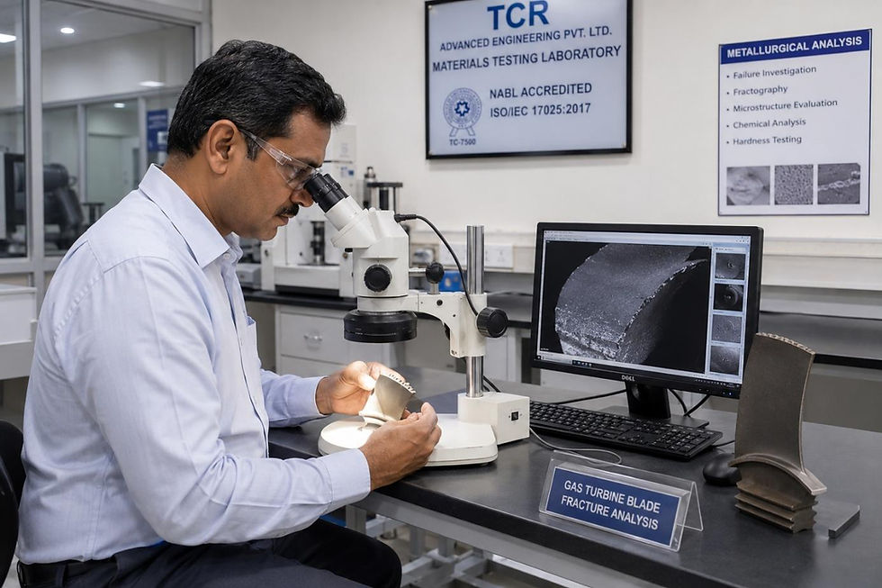
The primary screen is Time-of-Flight Diffraction (TOFD) ultrasonic testing. As carbon diffuses into the matrix and precipitates chromium and iron carbides, the affected layer's density, Young's modulus and Poisson's ratio all shift measurably from virgin material. TOFD reads the resulting change in diffracted-wave time-of-flight and can detect the presence of a carburised layer, and estimate its depth, without removing the tube from service.
That is precisely what makes it useful for both the fitness-for-service call and the remaining-life estimate that follows: it tells TCR Advanced which lengths of tube need a destructive look before any hardness or toughness number is even in hand.
On high-Cr-Ni tubes such as HK-40, this TOFD screen is supplemented with eddy current testing, since carbon uptake there also measurably increases ferromagnetism. That supplementary screen does not apply to P22, P5 or P9, since all three are already ferromagnetic; there is no ferromagnetic transition for an eddy current coil to detect. TCR Advanced backs the TOFD screen with a portable Vickers hardness reading at the flagged locations and in-situ metallography replication, reading grain-boundary carbide morphology without cutting the tube out of service.
Destructive
Only at locations the non-destructive screen flags, TCR Advanced pulls a boat sample for a full-thickness Vickers hardness traverse, Charpy impact testing and SEM/EDS carbon-concentration mapping, confirming both the carbon depth and the resulting toughness loss against the tube's remaining wall.
In this case, the non-destructive TOFD and replica screen located the carburised zone to a 1.2-metre length that visual inspection and thickness gauging at the prior turnaround had cleared as sound, precisely because wall loss was negligible. The destructive boat sample then confirmed case depth and toughness loss at that location.
FFS assessment and the RLA path
Because carburisation degrades toughness and ductility rather than wall thickness, the API 579-1/ASME FFS-1 assessment does not run through the general metal-loss levels most engineers reach for first. It runs through brittle fracture susceptibility (Part 3), using the measured hardness and toughness data from the metallography and boat-sample programme, cross-checked against a remaining-life estimate for the surrounding unaffected material using Larson-Miller parameter creep curves for the base metal still in its original ductile condition.
The TOFD survey is what defines the assessment boundary in the first place, since it identifies which tube lengths carry a carburised layer before any destructive sampling decision is made.
TCR Advanced's illustrative decision rule: where carburised case depth exceeds roughly 20–25% of remaining wall thickness, or measured hardness exceeds approximately 350 HV with a corresponding drop in Charpy energy below the material's minimum design toughness at the lowest anticipated metal temperature (startup, not steady state), the tube is called for replacement, regardless of what the UT thickness gauge shows. Where case depth is shallower and toughness margins hold, TCR schedules a shortened re-inspection interval, typically half the standard API RP 573 interval for that heater section, with TOFD, hardness and replica readings re-baselined at the same grid points so any progression is caught as a trend, not a surprise.
Prevention and next steps
The two carburisation triggers identified above are both decisions, not accidents, which means both are preventable.
Decoke on a fixed calendar. A tube spends less cumulative time generating a carburising atmosphere during the decoke itself when the decoke is scheduled, not run to failure. Steam-air ratio and temperature ramp need to be controlled tightly enough that the decoke does not become a carburisation event of its own.
Firing-rate discipline. Treat a falling outlet temperature as a coke-thickness alarm that triggers a decoke, not as a firing-rate problem to be solved by pushing more heat into a fouled coil.
For any P22, P5 or P9 heater section identified as carburisation-prone, TCR Advanced folds a TOFD survey and in-situ replica readings into the routine API RP 573 turnaround scope permanently, rather than treating carburisation assessment as a one-off forensic exercise. Results are logged in AiOM, so the hardness and TOFD trend, not just the wall-thickness trend, drives the next turnaround's tube-replacement list.
"Carburisation does not show up on a thickness gauge, on any of these tube grades. By the time a tube looks thin, it has usually been thick and brittle for years. We look at hardness and microstructure, because that is where this failure actually lives." — Paresh Haribhakti, Managing Director, TCR Advanced |
Frequently asked questions
What is high-temperature carburisation in fired heater tubes?
Carburisation is the diffusion of carbon into an iron-based alloy operating above 1100°F (593°C) in a carbon-rich, reducing environment, typically from coke contact or decoking activity. It raises hardness and reduces ductility and toughness without necessarily reducing wall thickness.
Which fired heater tube grades are at risk: P22, P5 or P9?
All three. API RP 571 lists carbon steel and low-alloy steels as susceptible above 1100°F (593°C) in a carbon-rich, reducing atmosphere. Carburisation resistance broadly improves with chromium content, so P9 (9Cr-1Mo) tolerates a given exposure somewhat better than P22 (2.25Cr-1Mo) or P5 (5Cr-0.5Mo), but none of the three is immune, and none approaches the resistance of a high-Cr-Ni alloy such as HK-40.
How does decoking cause carburisation?
Furnace tube decoking, whether steam-air or steam only, produces a carburising atmosphere at tube-wall temperatures where carbon diffusion is possible. Raising firing rate to compensate for a heavy coke deposit has the same effect, since it raises tube-wall temperature against the coke deposit generating the carbon activity.
Why does UT thickness gauging miss carburisation damage?
Carburisation degrades material toughness and ductility, not wall thickness. A tube can retain most of its original wall and still be at risk of brittle failure under thermal shock, so a thickness survey alone will not flag it.
How is carburisation detected on P22, P5 and P9 tubes?
TCR Advanced runs Time-of-Flight Diffraction (TOFD) ultrasonic testing as the primary non-destructive screen: carburisation shifts the affected layer's density and elastic properties enough to change diffracted-wave time-of-flight, which lets TOFD detect the presence and estimate the depth of a carburised layer without removing the tube from service. This is backed by portable hardness readings and in-situ metallography replication. Destructive boat-sample removal, Charpy testing and SEM/EDS carbon mapping are reserved for locations the non-destructive screen flags. Eddy current testing, the supplementary screen for austenitic HK/HP tubes, does not apply here because P22, P5 and P9 are already ferromagnetic.
What does the FFS path look like for a carburised tube?
The assessment runs through API 579-1/ASME FFS-1 Part 3 (brittle fracture), using the TOFD survey to define which tube lengths are affected, then measured hardness and toughness data from destructive sampling, cross-checked against a Larson-Miller-based remaining-life estimate for the unaffected base metal. TCR Advanced's illustrative decision rule flags replacement where case depth exceeds roughly 20–25% of remaining wall or hardness exceeds about 350 HV with toughness below the minimum design margin at startup metal temperature.


Comments