When a Turbine Blade Cracks: What Root Cause Analysis Reveals

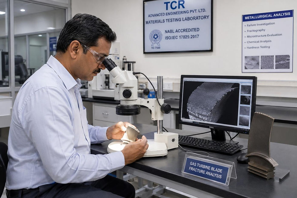
A gas turbine trips on high vibration at two in the morning. By the time the borescope goes in, the operator already suspects what it will find: a cracked first-stage blade, maybe a piece missing entirely. The turbine gets pulled apart, the blade gets replaced, and the unit is back online inside the week. Then, fourteen months later, a blade in the same stage fails again. This is the point where a proper Root Cause Analysis should have started the first time.
Gas turbine blades operate closer to the edge of what a material can survive than almost any other rotating component in an industrial plant, spinning at thousands of RPM inside a hot-gas path that can exceed the melting point of the alloy itself, kept intact only by cooling design and a coating a few hundred microns thick. When a blade fails, the fracture surface is evidence, not just damage. Read it correctly and you know exactly which mechanism to fix. Skip that step and replace the blade blind, and you're simply waiting for the next one.
Why "It Just Failed" Is Never the Full Answer
Turbine trips are expensive in ways that show up on more than one line of the P&L. A forced outage on a combined-cycle or open-cycle unit means lost generation, restart fuel burn, and often a contractual penalty on top. And that's before anyone accounts for the safety exposure of a rotor running at operating speed with a compromised blade, or the awkward position an operator is in when an insurer or regulator asks why the same failure mode has shown up twice.
A blade failure without a documented root cause isn't resolved. It's postponed.
Unplanned outage cost: restart fuel, lost generation, and penalty clauses accumulate fast on a repeat trip.
Consequential damage: a single liberated blade fragment can damage downstream stages, casings, and seals well beyond the original failure.
Safety exposure: a high-speed rotor failure is a high-energy event, not a routine maintenance item.
Asset life and warranty position: recurring failures without a traced cause weaken your case in any OEM or insurance claim.
What's Actually Killing Gas Turbine Blades
Six mechanisms account for most of the blade and vane failures TCR investigates, and they leave distinct signatures under a microscope.
Mechanism | Where It Shows Up | What's Driving It |
Hot Corrosion (HTHC / LTHC) | First-stage blades, nozzle guide vanes | Sulphidation from fuel or air-borne contaminants (sodium, vanadium, sulphur) at elevated temperature |
Creep | Blade root and airfoil, high-temperature stages | Prolonged operation near or above design temperature under sustained centrifugal load |
Thermo-Mechanical Fatigue | Leading and trailing edges, cooling holes | Repeated thermal cycling from start-stop operation and load transients |
Foreign Object Damage (FOD) | Compressor blades, leading edges | Ingested debris, ice, or loose hardware striking the blade at speed |
Coating Breakdown | Aluminide or MCrAlY-coated hot-gas-path blades | Spallation or oxidation of the protective coating, exposing base metal |
Corrosion Fatigue | Blade root fillets, dovetail attachments | Cyclic stress combined with a corrosive operating environment |
Hot corrosion deserves particular attention in the Indian operating context, where fuel quality and ambient air conditions vary widely across sites. Sodium and vanadium contaminants combine with sulphur at high temperature to attack the blade's protective oxide layer, and once that layer is compromised, the base metal degrades far faster than the design ever accounted for. Low-temperature hot corrosion tends to concentrate near the blade root, while the high-temperature form shows up closer to the tip, and telling the two apart matters because the corrective action, fuel treatment versus coating selection, is completely different.
The Chain That Leads to a Trip
A blade rarely fails for one isolated reason. The mechanisms above are usually the last link in a chain that started somewhere upstream in the operating envelope, and reconstructing that chain is the actual point of a root cause investigation.

A root cause investigation doesn't stop at identifying hot corrosion or fatigue on the fracture surface. It works backward through this chain until it reaches something an operator can actually act on, a fuel spec, a filtration upgrade, a coating change, a revised start-stop procedure.
What a Structured Investigation at TCR Looks Like

A credible gas turbine failure investigation draws on more than one discipline, and the sequence matters. Skipping a step, or running them out of order, is how investigations end up with an accurate description of the damage and no defensible root cause behind it.
Component Examination and Fractography
The failed blade, vane, or fragment is examined visually and dimensionally first, then under SEM-EDS to characterise the fracture surface: beach marks and striations point to fatigue, dendritic or intergranular features point to creep or overheat, and corrosion products on the surface point toward a chemical attack mechanism.
Metallurgical and Systems Review
Metallography, hardness testing, and coating thickness measurement establish whether the microstructure matches what the operating hours and temperature history would predict. Alongside this, TCR reviews the operational context that fractography alone can't reveal: fuel quality records, compressor inlet air filtration, start-stop frequency, and any recent deviation from the normal operating envelope.
"A fracture surface tells you what happened in the last few minutes of a blade's life," says Paresh Haribhakti, Managing Director of TCR Advanced Engineering. "The operating history tells you why it got there. You need both to write a root cause that actually holds up."
Auxiliary systems matter too. Where a heat exchanger or intercooler feeds into the turbine's inlet or cooling circuit, degraded performance there can quietly raise hot-gas-path temperatures and accelerate exactly the mechanisms in the table above, so a thorough investigation checks upstream systems rather than assuming the hot-gas path acted alone.
Getting the Root Cause Right the First Time
A turbine blade that fails once is a data point. A turbine blade that fails twice in the same stage, on the same unit, is a root cause that hasn't been found yet. Reliable gas turbine operation depends on catching that difference early, before a fatigue crack or a corrosion-thinned coating turns into a forced outage with consequential damage attached.
A structured failure and root cause analysis isn't paperwork after the fact. It's the difference between replacing a blade once and replacing the same blade every operating season.
Frequently Asked Questions
Q: What's the difference between a failure investigation and a root cause analysis for a gas turbine?
A: A failure investigation identifies what failed and how, a cracked blade, a fatigue fracture, a coating breakdown. Root cause analysis goes a step further and asks why the conditions existed that allowed that failure to happen. In practice, both usually run together as one investigation, which is why the two terms tend to be used interchangeably.
Q: How is hot corrosion told apart from creep or fatigue on a failed blade?
A: Under SEM, each mechanism leaves a distinct signature. Fatigue shows beach marks and striations on the fracture surface. Creep shows dendritic or intergranular features from prolonged high-temperature exposure. Hot corrosion shows characteristic surface attack and corrosion products. Telling them apart correctly matters because the fix, a coating change versus a fuel spec change versus an operating limit, is different for each.
Q: How soon after a trip should the investigation begin?
A: As soon as the unit is safely secured. Fracture surfaces and deposit chemistry can degrade or get contaminated with handling and time, and the earlier the sample and operating logs are captured, the more reliable the root cause finding will be.
Q: Can a problem in an auxiliary system, like a heat exchanger, really cause a blade failure?
A: Yes. A heat exchanger or intercooler feeding into the turbine's inlet or cooling circuit can quietly raise hot-gas-path temperatures if it's underperforming, which accelerates hot corrosion, creep, or coating breakdown on the blades. That's why a thorough investigation checks upstream systems rather than assuming the hot-gas path failed in isolation.
Q: What does a gas turbine failure investigation report actually include?
A: An executive summary, the incident chronology from operating logs and alarm data, visual and fractography findings, metallurgical results, a review of supporting systems, and a root-cause chain linking the failure back to its origin, along with specific corrective and preventive recommendations rather than general advice.
At TCR Advanced Engineering, our team of metallurgical and asset integrity specialists has supported over 1,800 clients across power, oil & gas, refinery, petrochemical, and manufacturing sectors. With 10,000+ failure investigations behind us and 500+ years of cumulative team expertise, we bring SEM-EDS fractography, in-situ metallography, and a disciplined investigation methodology to trace gas turbine and rotating equipment failures to their true root cause. Reach out to our team or learn more about our Failure Investigation and Asset Integrity Management services at www.tcradvanced.com. |


Comments