Structural Integrity Services
17 September 2026
Know what your structure can still carry, and for how long.
Condition assessment, stability study and remaining-life evaluation of steel and RCC structures in operating plants. Field NDT, laboratory testing and engineering analysis under one accredited signature.
[ Hero buttons (add as elements): “Discuss a structure” → Contact/Enquiry, and “How we assess” → anchor to the methodology section ]
The structure is part of the pressure boundary's safety case
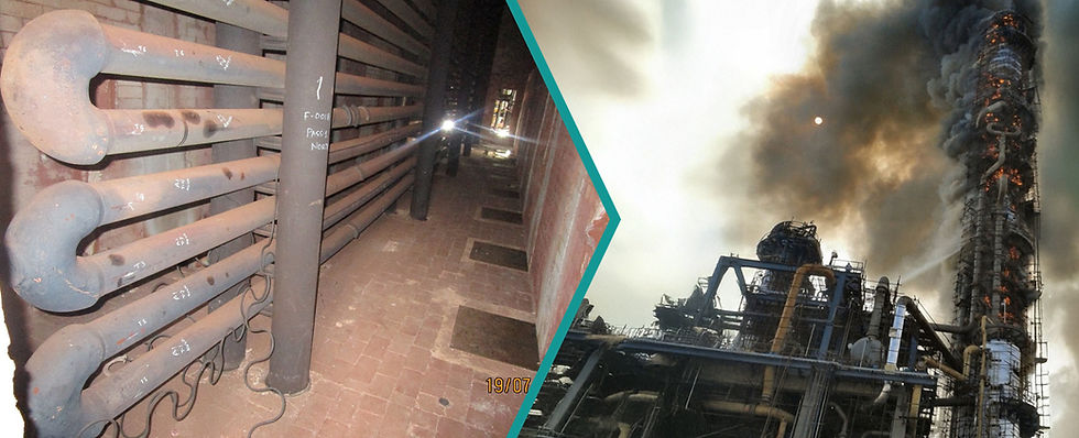
Every vessel, exchanger, pipe rack, crane and stack in a plant stands on a structure that was designed once and has been corroding, overloaded and modified ever since. Mechanical integrity programmes cover the equipment in detail and the structure under it hardly at all. That gap is where columns lose section to corrosion, RCC pedestals lose cover to carbonation and chloride, and crane girders drift out of alignment.
Our structural integrity service closes the gap. We measure the as-found condition of the steel or concrete with NDT and laboratory testing, compare it with the design basis and the applicable Indian and international codes, and give you a signed engineering position: fit for continued service, fit with repair, or not fit, with the remaining life and the next inspection date stated.
Steel and RCC, above and below ground
Metallic and steel structures
Columns, beams, bracing, connections, pipe racks, crane girders and monorails, stacks, platforms and equipment support frames.
Corrosion section loss, generalised and localised, with rate estimation
Weld and connection condition: cracking, bolt loss, distortion
Verticality, alignment and deflection against permissible limits
Material verification: hardness, in-situ metallography, PMI where grade is unknown
Capacity check to IS 800:2007 with the measured residual section
Remaining useful life from measured loss and corrosion rate, with stated uncertainty
RCC structures
Columns, beams, slabs, equipment foundations and pedestals, silos, cooling-tower basins, pits, trenches and underground structures.
Concrete quality and homogeneity by rebound hammer and ultrasonic pulse velocity
Reinforcement corrosion risk: half-cell potential, carbonation depth, chloride and sulphate content
In-place compressive strength from extracted cores
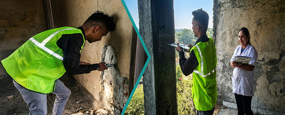
Cover, cracking, spalling, settlement and tilt survey
Capacity check to IS 456:2000 with the measured in-place strength
Repair specification and residual-life position for the structure
Field measurement backed by an accredited laboratory
Every field method below is run to a written standard. Cores, chips and coupons go to our NABL-accredited laboratory (TC-6739) so the numbers that enter the calculation carry traceability and uncertainty.
Steel structures: NDT and DT
Visual and dimensional examination (IS 800, site protocol): distortion, corrosion pattern, missing members, additions and alterations
Ultrasonic thickness gauging (ASTM E797): residual section of flanges, webs, tubes; loss vs. design
Dye penetrant testing (ASTM E165, E1417): surface cracks at welds and connections
Magnetic particle testing (ASTM E709, E1444): surface and near-surface cracks in ferromagnetic members
Portable hardness (UCI) (ASTM A1038): grade confirmation, heat damage, weld HAZ hardness
Verticality and alignment survey (total station, 3D laser scan): tilt, sway, crane-rail alignment, deflection
Strain gauging under load (site protocol): actual member stress against calculated
In-situ metallography and PMI (ASTM E1351, E1476): microstructure and grade without cutting the member
RCC structures: NDT and DT
Rebound hammer (IS 13311 Pt 2): surface hardness, relative strength, uniformity
Ultrasonic pulse velocity (IS 13311 Pt 1): concrete quality grading, voids, cracks, honeycombing
Half-cell potential (ASTM C876): probability of active rebar corrosion, mapped
Carbonation depth (BS 1881-201, phenolphthalein): depth of alkalinity loss vs. cover
Core extraction and compression (IS 516): in-place compressive strength for the capacity check
Chemical analysis of concrete (laboratory, TC-6739): pH, chloride and sulphate content; mix proportion
Cover and rebar survey (profometer, site protocol): cover depth, bar spacing and diameter vs. drawings
Verticality and settlement survey (total station): tilt, differential settlement, crack monitoring
From measured condition to a signed capacity decision
Measurement alone does not answer the owner's question. We rebuild the structural model from the drawings, replace design sections with measured residual sections and design strengths with tested in-place values, and re-check capacity against the governing code: IS 800:2007 for steel, IS 456:2000 for concrete, with loads to IS 875 and seismic demand to IS 1893. AISC 360 and ACI 318 are applied as cross-checks or where the client's basis is international.
Where the geometry or loading is not amenable to hand calculation, or where wind and seismic load not envisaged at the time of design must be examined, we model the structure in finite-element software (STAAD.Pro, ANSYS). The model locates the governing stress, tests proposed strengthening, and settles the remaining-life projection with the corrosion rate and its uncertainty stated, not assumed away.
The deliverable is a structural stability report signed by the Managing Director, and where the client requires it, the stability certificate in the form prescribed under the Factories Act and the State Factories Rules.
The decision rule we report against
t greater than 1.5 x t_allow: Fit for service. Remaining life beyond horizon; inspection interval set.
t_allow to 1.5 x t_allow: Fit, rate-limited. Remaining life computed from measured corrosion rate; monitoring or repair scheduled.
t below t_allow: Not fit as-is. Immediate load reduction, strengthening or replacement; escalated before the report closes.
t = measured residual thickness; t_allow = thickness required for design load to IS 800:2007 with the buckling check. Remaining useful life carries the measurement tolerance and the corrosion-rate bound.
Four phases, one report
1. Document review
Approved structural plans, design calculations, load data, material certificates, past NDT and maintenance records. Critical and non-redundant members identified before site work.
2. Site inspection and testing
Visual survey, loading compatibility with intended use, additions and alterations, then the NDT and DT programme on the members that govern.
3. Analysis
Capacity check with measured sections and strengths, FEA where required, corrosion-rate and remaining-life calculation with uncertainty.
4. Report and certificate
Findings, calculation basis, fitness decision, repair scope, inspection interval, and the stability certificate where required.
Anything that carries process equipment, people or load
Equipment support frames
Vessel and exchanger structures, skirts, saddles, pedestals
Pipe racks and supports
Racks, sleepers, spring and rigid supports, piers
Crane and lifting structures
EOT crane girders, gantries, monorails, rail alignment
Stacks, silos, cooling towers
Self-supported steel and RCC stacks, bins, basins
Factory buildings and sheds
Portal frames, trusses, mezzanines, Factories Act stability
Heater and boiler structures
Fired-heater steel, boiler supporting structures
Foundations and underground
Machine foundations, pits, trenches, tanks
Jetties and marine
RCC and steel jetty structures in chloride exposure
Industries served: refineries and petrochemicals, fertiliser, power, chemicals and pharmaceuticals, steel and metals, EPC, manufacturing, insurance surveys.
The corrosion mechanism, not just the thickness reading
One accredited signature
Field NDT, laboratory testing, structural calculation and the stability certificate from one firm, signed by the Managing Director, under NABL TC-6739 and NADCAP AC7101.
Metallurgy behind the number
10,000+ failure investigations and a 1,50,000+ microstructure database. We identify why the steel or rebar is corroding, so the remaining-life projection rests on the mechanism.
Numbers with uncertainty
Measurement tolerance, corrosion-rate bound and decision rule stated in the report. A remaining life is given as a range with a confidence level, never a bare point value.
Integrated with plant integrity
Structural findings feed the same AiOM asset register as your vessels, piping and RBI programme, so the structure is inspected on the same rhythm as the equipment it carries.
Standards applied
IS 800:2007
IS 456:2000
IS 875 (Pt 1-3)
IS 1893
IS 13311 (Pt 1, 2)
IS 516
ASTM E797
ASTM E165 / E709
ASTM A1038
ASTM C876
BS 1881
AISC 360
ACI 318
API 583
Accreditations: NABL TC-6739 (ISO/IEC 17025:2017) · NADCAP AC7101 · Recognised Research Institution, MS University, Vadodara.
Tell us about the structure
Send the structure type, its age, what you have observed and any drawings you hold. A structural engineer responds with a scope and a site plan, not a form reply.
[ Add the enquiry form here as a Wix Form element: fields Name, Company and email, Structure type (dropdown: Steel structure/pipe rack/frame; Crane girder/gantry/monorail; RCC structure/foundation; Stack/silo/cooling tower; Factory building stability certificate; Other), Brief; submit button “Send to an engineer” ]
TCR Advanced Engineering Pvt. Ltd.
Head office and laboratory: 250-252/9, GIDC Estate, Makarpura, Vadodara 390 010, Gujarat, India
Email: testing@tcradvanced.com
Telephone: +91-7574805594-96
Accreditation: NABL TC-6739 (ISO/IEC 17025:2017) · NADCAP AC7101


.png)
.png)

-2.jpg)



%20as%20per%20API-1104-2.jpg)