.png)
Mechanical Testing in Engineering: What Every Plant Owner and Design Engineer Must Know


A bridge doesn't fail the day it collapses. It fails years — sometimes decades — earlier, the moment a specification was approved without a proper compression test, or a TMT bar passed through quality control because nobody ran a re-bend test. The collapse is just when we notice.
Mechanical testing is, at its core, the science of making materials prove themselves before we trust them with human lives and industrial assets. But here's what's often misunderstood: these tests aren't just about checking a box for a government inspector or an insurance auditor. Done right, they give you a precise, quantified picture of how a material or structure will behave under the exact conditions it will face — load, stress, deformation, fatigue, or anchorage failure.
This blog covers every major mechanical test — from the fundamental compression test and load test to the often-overlooked pull-out and push-out tests — and explains what each one actually tells you, why it matters, and when you need it.
Five Families of Mechanical Testing — and Why the Grouping Matters
Engineers often think of mechanical tests in isolation — 'we need a tensile test' or 'the client wants a hardness check.' But the more useful frame is to group tests by what they're designed to reveal. This shapes not just which test you run, but what specimens you prepare, what standards you follow, and how you interpret the results.
The table below maps all major tests covered in this blog to their category, applicable standards, and primary outcome:
Test Category | Key Tests Covered | Relevant Standards | Primary Outcome |
Compression & Load Testing | Compression Test, Load Test, Proof Load Test, Cantilever Test | IS 516, ASTM C39, BS EN 12390 | Ultimate compressive strength, structural load capacity |
Steel & Rebar Testing | TMT Bar Test, Bend Test, Re-bend Test, Tensile & Bend Test | IS 1786, IS 1608, ASTM A615 | Yield strength, UTS, ductility, bendability |
Dimensional & Surface Evaluation | Dimension Measurement, Surface Roughness Test, Bulk Density | IS 2102, ISO 4287, IS 2386 | Geometric conformance, Ra/Rz values, mass per unit volume |
Stress–Strain & Displacement Analysis | Load vs Displacement, Stress vs Strain, Stress vs Displacement Curves | ASTM E8, ISO 6892, ASTM E1823 | Material behaviour under load, energy absorption, failure mode |
Anchorage & Pull Testing | Strain Wire Testing, Pull Testing, Pull-Out / Push-Out Test | ASTM E488, IS 2751, fib Model Code | Bond strength, anchorage capacity, interface shear resistance |
Let's go deeper into each family.
Compression Test, Load Test & Proof Load Test: The Backbone of Structural Qualification
These three tests are the foundation of structural material qualification — and they're frequently confused with each other, which causes real problems when specifications are written.
Compression Test
A compression test applies a uniaxial compressive force to a specimen — typically concrete cube or cylinder, ceramic, polymer, or metal — until failure or until a defined deformation limit is reached. The primary output is compressive strength (MPa), but the load-deformation behaviour captured during the test tells you far more: stiffness, brittleness, the presence of internal voids or cracks, and the mode of failure.
For concrete specifically, IS 516 and BS EN 12390-3 govern the test procedure. Specimen preparation — curing, capping, and age at testing — directly affects results. A 7-day and 28-day pair of compression tests isn't just a formality; it's the only way to verify that the concrete's strength gain trajectory matches the design assumption.
Load Test
A load test applies a defined external force to an actual structure or structural element — not a laboratory specimen — to verify it can carry its design load without excessive deformation or failure. Load tests are commonly performed on floors, bridges, piles, anchors, and lifting equipment. The critical output isn't just 'did it hold?' — it's the load-vs-displacement behaviour over the full loading cycle, including unloading and recovery.
Any permanent set (residual deformation after load removal) beyond the acceptable limit is a red flag, even if the structure didn't collapse under test load.
Proof Load Test
A proof load test is a specific type of load test where the applied load is set at a defined multiple of the working load — typically 1.5× to 2× — to 'prove' the structure or component is fit for service. It's common for lifting equipment, crane hooks, slings, and pressure vessels. The component must sustain proof load without permanent distortion, cracking, or failure.
Don't confuse proof load with ultimate load. Proof load testing doesn't take the component to failure — it verifies a margin of safety exists.
Cantilever Test
A cantilever test applies a transverse load at the free end of a fixed beam or arm to evaluate bending strength, stiffness, and deflection behaviour. It's particularly relevant for brackets, shelf structures, boom arms, and overhang elements. The test directly generates a load-vs-deflection curve and helps validate design calculations — especially for elements subject to dynamic or eccentric loading in service.

TMT Bar Test, Bend Test, Re-bend Test & Tensile–Bend Test: Getting Rebar Right
Rebar testing is one of the most critical and — in India — most frequently compromised areas of mechanical testing. The construction industry's dependence on Thermo-Mechanically Treated (TMT) bars for reinforced concrete structures makes the quality of these tests directly relevant to structural safety at a national scale.
TMT Bar Test
A TMT bar test battery typically includes tensile testing (yield strength, UTS, percentage elongation), bend testing, re-bend testing, and dimensional measurements (weight per metre, cross-sectional area). IS 1786 is the governing standard in India, with Grade Fe 415, Fe 500, Fe 500D, and Fe 550D each having specific mechanical property requirements.
One thing that's often skipped: the elongation measurement. Plants focused on yield and UTS numbers miss the fact that a bar with marginal elongation will behave in a brittle manner under seismic loading — exactly when ductility matters most.
Bend Test
A bend test wraps a rebar specimen around a mandrel of specified diameter (defined by the bar diameter and grade) through 180° without developing surface cracks, fractures, or delamination. It's a direct check on the steel's ductility and the integrity of the outer surface — where thermos-mechanical treatment creates the hardened martensitic layer.
A bar that fails a bend test has either poor ductility, excessive carbon content, or surface defects that indicate a problem in the rolling or quenching process.
Re-bend Test
The re-bend test is more demanding — and more revealing. The bar is first bent to a specified angle (typically 45°), aged at 100°C for one hour (to simulate strain ageing in service), and then bent back. The specimen must survive without cracking.
Strain ageing embrittlement is a real phenomenon in certain steel chemistries. The re-bend test is the only test that specifically checks for it. For structures in seismic zones or subject to repeated loading cycles, a rebar that passes tensile and bend tests but fails the re-bend test is not suitable — full stop.
Tensile & Bend Test on the Same Specimen
In some protocols — particularly for weld procedure qualification and structural steel sections — tensile and bend tests are performed on the same specimen set as a combined evaluation of the material's overall mechanical performance. The tensile test establishes strength properties; the bend test confirms ductility. Together, they give a complete picture that neither test provides alone.
Dimension Measurement, Surface Roughness & Bulk Density: The Underrated Trio
These three tests are often treated as 'housekeeping' — quick checks done to satisfy a QC checklist. That's the wrong mindset. Each one, when done rigorously, reveals information that directly affects how a component performs.
Dimension Measurement Test & Test Specimens for Mechanical Testing
Before any mechanical test can be trusted, the specimen dimensions must be verified. Cross-sectional area, gauge length, and specimen geometry are direct inputs into the stress and strain calculations. An error in measurement of as little as 0.5 mm in gauge length affects the reported elongation value — and therefore the compliance assessment.
IS 2102 and ISO 286 define dimensional tolerances for engineering components. For rebar, weight per metre is a proxy for cross-sectional area — but only valid if the density assumption is correct and the surface geometry is within tolerance. Under-weight bars are a chronic issue in the Indian market.
Surface Roughness Test & Surface Roughness Evaluation
Surface roughness — quantified as Ra (arithmetical mean deviation) or Rz (mean roughness depth) per ISO 4287 — affects fatigue life, friction coefficient, sealing performance, and coating adhesion. A machined shaft running in a bearing that's 2 µm rougher than specified will wear out its bearing in a fraction of the design life. A pipeline coating applied over a surface that hasn't met Sa 2.5 cleanliness and the specified roughness profile will delaminate under thermal cycling.
Surface roughness evaluation goes beyond running a profilometer. It requires understanding which parameter (Ra, Rz, Rt, Rq) is relevant for the application, measuring in the correct direction relative to machining marks, and interpreting the result in context.
Bulk Density
Bulk density matters most for granular and aggregate materials — sand, gravel, crushed stone, refractory materials, and powders. It measures mass per unit volume of material in its natural packed state, including interparticle voids. IS 2386-III governs bulk density for aggregates used in concrete.
For refractory materials — used extensively in furnaces, kilns, and boilers — bulk density is a key indicator of thermal insulation performance and structural integrity under thermal shock. Low bulk density in a castable refractory means higher porosity, which means faster thermal degradation and reduced service life.
Load vs Displacement, Stress vs Strain, Stress vs Displacement: Reading the Curve Correctly
These three output graphs — generated during mechanical testing — are arguably the most information-rich outputs in all of material characterisation. And yet they're routinely reduced to a single pass/fail number. That's leaving most of the value on the table.
Curve Type | X-Axis | Y-Axis | What It Reveals | Typical Use Case |
Load vs Displacement | Displacement (mm) | Applied Load (kN) | Stiffness, yield point, failure load, energy absorption | Structural elements, pull-out tests, beam deflection |
Stress vs Strain | Strain (mm/mm or %) | Stress (MPa) | Young's modulus, yield strength, UTS, elongation | Material qualification, tensile testing per IS/ASTM |
Stress vs Displacement | Displacement (mm) | Stress (MPa) | Material response at specific cross-section under deformation | FEA validation, weld joint behaviour, anchor bolt testing |
The shape of a stress–strain curve tells you far more than the numbers at the endpoints. A sharp, well-defined yield point followed by a plateau (Lüders band behaviour) looks very different from a gradual, continuously curving yield — and the difference has practical implications for forming, welding, and service behaviour. A load–displacement curve from a pull-out test that shows a sudden drop is telling you about a brittle bond failure — very different from a gradual softening that signals ductile yielding of the matrix.
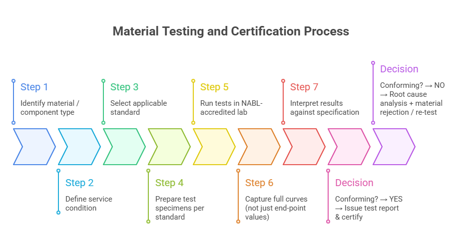
Any lab that hands you a single number without the curve is giving you a fraction of what you paid for.
Strain Wire Testing, Pull Testing & Pull-Out / Push-Out Tests: Anchorage at the Limit
These tests sit at the intersection of materials science and structural engineering — and they're among the most practically consequential tests a lab can run. Get the anchorage wrong, and you lose the structure.
Strain Wire Testing
Strain wire (or strain gauge wire) testing involves bonding electrical resistance strain gauges to a structural element — beam, column, pressure vessel, or bridge deck — and monitoring the electrical resistance change as the element deforms under load. The resistance change converts directly to strain via the gauge factor.
This isn't a destructive test. It's often used for in-situ structural health monitoring, load testing of existing structures, or validating FEA models against actual behaviour. The output is a continuous strain record — which, when combined with geometry and material properties, gives you stress distribution across the section.
Pull Testing
A pull test applies a direct tensile force to an anchor, fastener, bolt, weld, or reinforcing element and measures the force at which it withdraws from the base material, fractures, or reaches a defined displacement limit. Pull testing is mandatory for post-installed anchors per ASTM E488, and for checking anchor bolt installations in structural steelwork, machinery foundations, and pipeline supports.
The critical distinction: a pull test that reaches the specified proof load without failure or excessive displacement is a pass. But the load–displacement curve at that pass is also telling you about the stiffness and ductility of the anchorage — information that matters under dynamic or seismic loading.
Pull-Out / Push-Out Test
The pull-out test specifically measures the bond strength between two materials — most commonly between a reinforcing bar and the surrounding concrete matrix. The rebar is embedded in a concrete block or cylinder and pulled in tension until the bond fails. Failure mode matters as much as the failure load: a rebar that pulls out cleanly without taking concrete with it has failed at the interface; one that fails with a cone of concrete attached has failed through the matrix — very different structural implications.
The push-out test is the inverse: a shear connector (typically a headed stud welded to a steel beam flange) is embedded in a concrete slab and pushed in shear until failure. It directly measures the shear stud's load-slip behaviour — the fundamental input for composite beam design per Eurocode 4 or IS 11384.
Both tests generate a load–displacement or load–slip curve. The initial stiffness, peak load, post-peak behaviour, and failure mode together define the anchorage's complete structural performance — not just one number.

The TCR Advanced Perspective: Why Lab Accreditation Is Non-Negotiable
Here's a truth the industry doesn't say loudly enough: not all test reports are equal. A compression test run in a NABL-accredited lab under ISO/IEC 17025 quality management is not the same as one run in an unaccredited facility — even if the equipment looks identical.
NABL accreditation requires documented calibration of every instrument, traceable to national standards. It requires defined uncertainty budgets for every measurement. It requires trained and assessed personnel, proficiency testing, and audited procedures. The test report from an accredited lab isn't just a number — it's a defended number with a known uncertainty.
For procurement decisions, insurance claims, litigation, and regulatory submissions, that distinction is the difference between evidence and opinion.
At TCR Advanced Engineering, our NABL-accredited Material Testing Laboratory — operating under ISO/IEC 17025 — covers the full range of mechanical, metallurgical, chemical, and corrosion tests discussed in this blog. We don't just run the test and hand over a number. We look at the full curve, flag anomalies, and — where relevant — connect the test result to the component's actual service condition and failure risk. That's the difference between a testing lab and an engineering consulting firm.
Conclusion: The Test Is Not the Point — the Decision Is
Mechanical testing exists to inform decisions. Which material to approve. Whether a structure is safe to load. How much life is left in an ageing anchor bolt. Whether a TMT bar will hold under seismic excitation or snap in a brittle mode.
Mechanical testing exists to inform decisions. Which material to approve. Whether a structure is safe to load. How much life is left in an ageing anchor bolt. Whether a TMT bar will hold under seismic excitation or snap in a brittle mode.
The tests covered in this blog — from the compression test to the pull-out/push-out test — are not independent silos. They form an interconnected vocabulary for describing how materials and structures behave under real-world conditions. A plant manager who understands that vocabulary can ask better questions, make better procurement decisions, and avoid the expensive surprises that come from trusting a number without understanding what it means.
The organisations that treat mechanical testing as a quality gateway — not just a compliance exercise — are the ones whose assets stay in service longer, whose structures perform as designed, and whose maintenance budgets stay predictable. That's not an aspiration. It's what the data consistently shows.
FAQs
1. What is mechanical testing in engineering?
Mechanical testing is the process of evaluating how materials and structural components behave under forces like tension, compression, bending, and shear to ensure safety, strength, and reliability before real-world use.
2. Why is the compression test important in construction materials?
A compression test determines the compressive strength of materials like concrete and ceramics, helping engineers confirm whether a structure can safely carry expected loads without failure.
3. What is the difference between a load test and a proof load test?
A load test checks how a structure performs under working conditions, while a proof load test applies a higher predefined load (usually 1.5×–2× working load) to verify safety margins without causing failure.
4. What does a TMT bar test include?
A TMT bar test typically includes tensile strength, bend test, re-bend test, and dimensional checks to ensure ductility, strength, and suitability for reinforced concrete structures.
5. Why is the re-bend test critical for TMT bars?
The re-bend test checks resistance to strain ageing. It ensures the steel does not crack after bending and re-bending, which is crucial for seismic safety and long-term structural performance.
6. What is the purpose of a pull-out or push-out test?
Pull-out and push-out tests evaluate the bond strength between reinforcement and concrete or shear connectors, helping determine anchorage performance and interface strength under real conditions.
7. Why should mechanical testing be done in NABL-accredited labs?
NABL-accredited labs like TCR Advanced Engineering follow ISO/IEC 17025 standards, ensuring accurate, traceable, and reliable test results with defined measurement uncertainty—critical for engineering decisions, compliance, and safety.
At TCR Advanced Engineering, our NABL-accredited Material Testing Laboratory has supported over 1,800 clients across manufacturing, construction, petrochemical, power, and EPC sectors with precise, standards-compliant mechanical testing — from routine TMT bar tests and compression tests to advanced pull-out/push-out evaluations, surface roughness assessments, and full stress–strain curve characterisation. With 9,500+ investigations behind us and 500+ years of cumulative team expertise, we bring the rigour your critical decisions deserve. If you're specifying materials, qualifying a weld procedure, validating a structural design, or investigating an unexpected failure — talk to us first. Visit www.tcradvanced.com or reach out to our testing team to discuss your requirements. |


Comments